

Network setup with standard hardware
How the internal network of a Rosepetal deployment is configured using the standard project hardware.
The standard equipment of a Rosepetal project is mounted in the AIS rack and includes:
| Equipment | Function |
|---|---|
| Router (Teltonika RUT901) | Internet uplink (DHCP or client IP) and remote access point |
| Switch | Camera network (2.5 Gbps) |
| Rosepetal Controller | Runs the Rosepetal software: inference, logic and camera management |
| Panel PC | Operator interface on the plant floor |
| Cameras | Image capture on the production line |
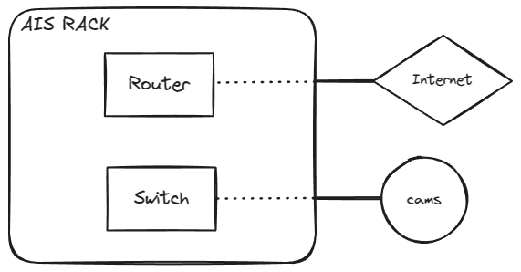
Internal network scheme
Standard example with 4 cameras:
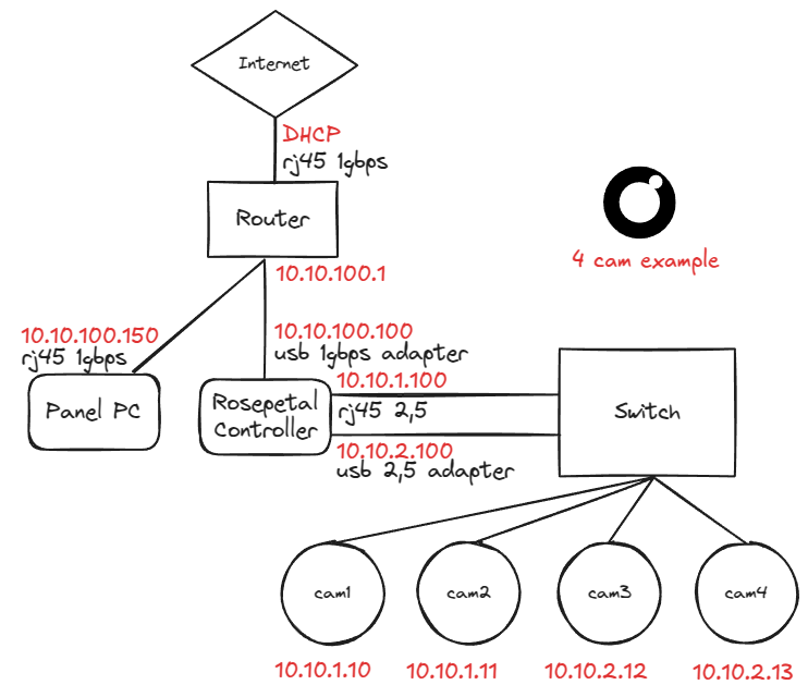
Reference addressing and connections:
| Equipment | Interface | IP |
|---|---|---|
| Router | WAN (rj45 1 Gbps, DHCP to internet) | client-defined |
| Router | LAN | 10.10.100.1 |
| Panel PC | rj45 1 Gbps to router | 10.10.100.150 |
| Rosepetal Controller | USB 1 Gbps adapter to router | 10.10.100.100 |
| Rosepetal Controller | rj45 2.5 Gbps to switch (camera network 1) | 10.10.1.100 |
| Rosepetal Controller | USB 2.5 Gbps adapter to switch (camera network 2) | 10.10.2.100 |
| cam1 / cam2 | switch | 10.10.1.10 / 10.10.1.11 |
| cam3 / cam4 | switch | 10.10.2.12 / 10.10.2.13 |
Design criteria
- The management network (
10.10.100.x: router, Panel PC, Controller) is kept separate from the camera networks (10.10.1.x,10.10.2.x), split across two 2.5 Gbps interfaces of the Controller to maximize capture bandwidth. - The Controller is the only device present in both scopes; the cameras never have internet access.
- The router gets internet from the client via DHCP or fixed IP (rj45 1 Gbps).